
CHALLENGE: Design, build, test, and launch a high-powered rocket carrying a scientific payload.
SUMMARY: This project outlines the design, development, and testing of a launch vehicle and payload for the NASA University Student Launch Initiative. The rocket features a dual-deployment system for parachute recovery of the launch vehicle, as well as a robust airbrake mechanism and a deployable glider payload. Engineered to withstand the stresses of high-speed flight, the rocket consists of a custom-fabricated composite airframe to ensure structural integrity and optimum weight. Static fire tests, vibration testing, subscale launches, and flight simulations, were conducted to validate the rocket's reliability.
COURSE/CLIENT: NYU Vertically Integrated Projects, NASA, Rogue Aerospace
COMPLETION: April 2024
SKILLS: Low Voltage Electronics, Microcontrollers, Servo/Actuators, Radio Engineering, Solid Rocket Propulsion, Aerodynamics, Linkage Design and Mechanisms, 3D Printing, Subtractive Manufacturing, Fiberglass and Carbon Fiber Molding, Project Management, Testing Documentation
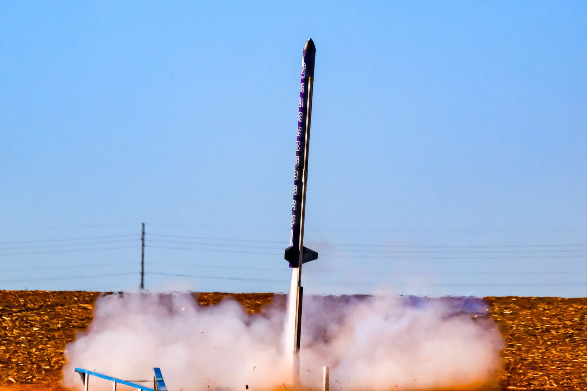
Sisyphus Liftoff, Photo by Jim Wilkerson
NYU ROGUE AEROSPACE
New York University’s aerospace team, Rogue Aerospace, competes in NASA USLI. The competition is a 9-month long design process and tasks student teams from across the U.S. to design, build, test, and launch a high-powered rocket carrying a scientific payload. Rules are released in the fall and the teams launch in the spring in Huntsville, Alabama.
In 2024, I led a team of 5 subteams and 40 engineers as Engineering Director in the NASA USLI competition, We created Sisyphus, a reusable rocket capable of launching into the sky, slowing down to a specific altitude, ejecting a payload and parachutes, and landing safely. Rock is the payload, a nose cone folding glider, designed to contain four miniature crewmembers. 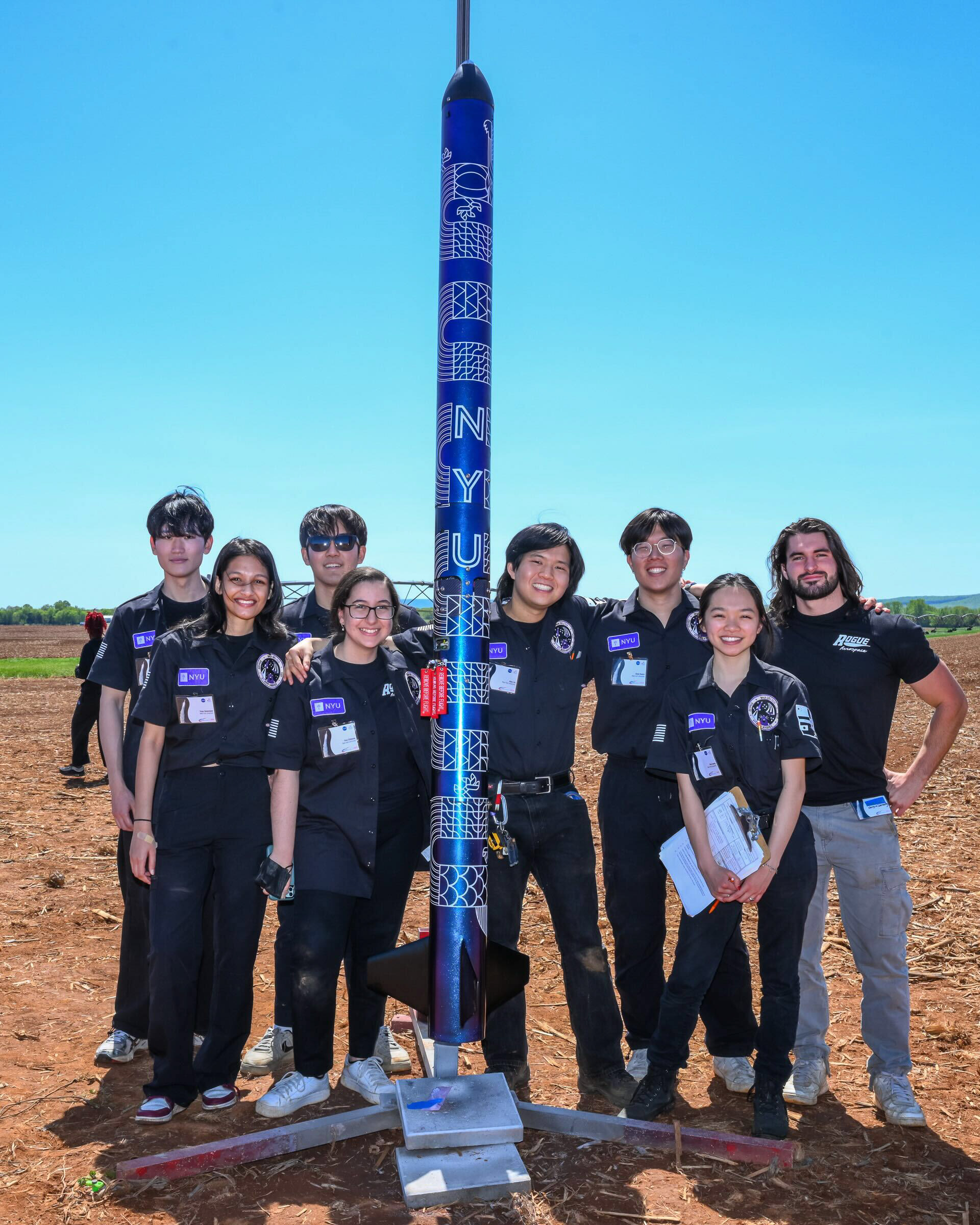
Left to Right: Nuri Han, Triparna Dewanjee, Noel Kim, Tina Chibane, Alex Xu, Dave Kwon, Zoe Leung, Alex Miller, Photo by Jim Wilkerson
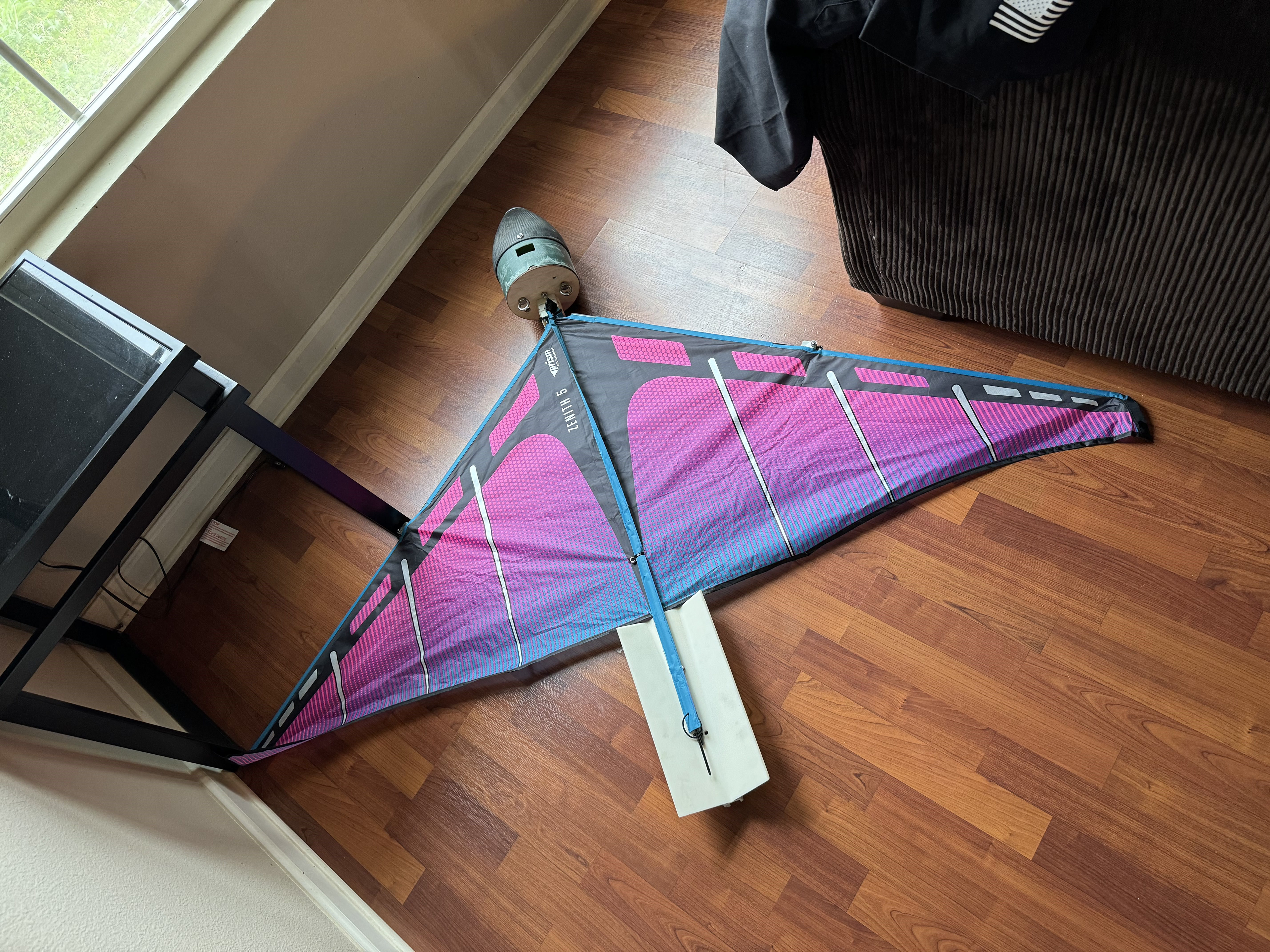
Unfolded Glider
PAYLOAD ENGINEERING SYSTEMS
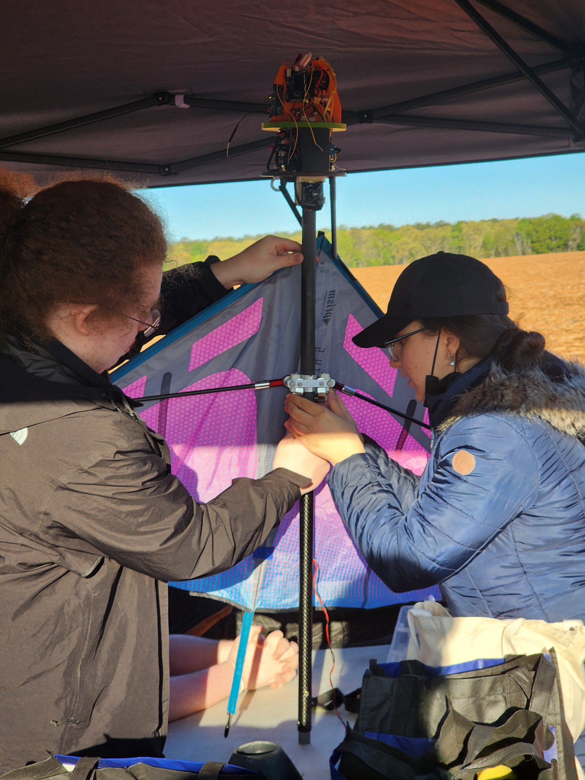
The payload ejects from the rocket via radio control. After ejecting, its tail selfrights the payload and a delta wing kite unfolds from the nose cone to reduce the descent velocity. Rock uses carbon fiber rods and tubes for its body and wings with aluminum in its folding mechanisms for maximizing strength and reducing weight. Rock transmits live video, GPS, and altitude data back to the team's ground station.
The payload ejects from the rocket via radio control. After ejecting, its tail selfrights the payload and a delta wing kite unfolds from the nose cone to reduce the descent velocity. Rock uses carbon fiber rods and tubes for its body and wings with aluminum in its folding mechanisms for maximizing strength and reducing weight. Rock transmits live video, GPS, and altitude data back to the team's ground station.
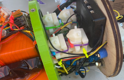
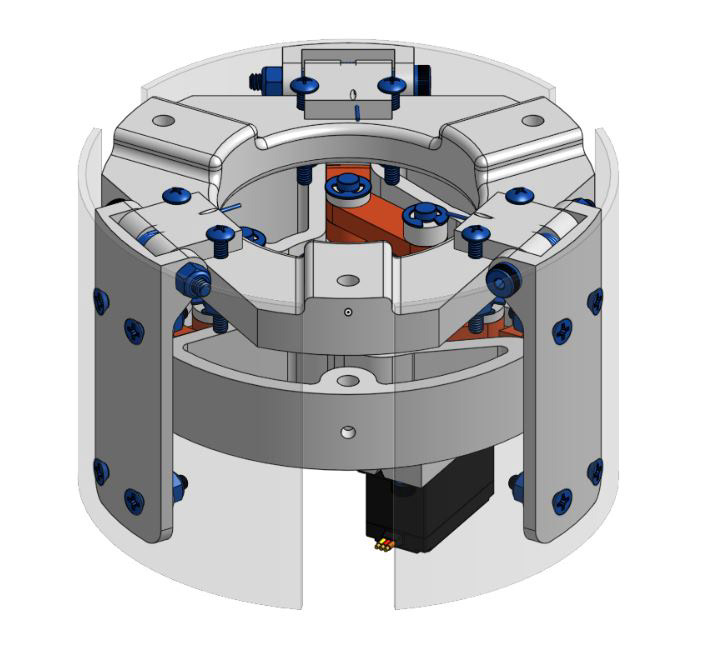
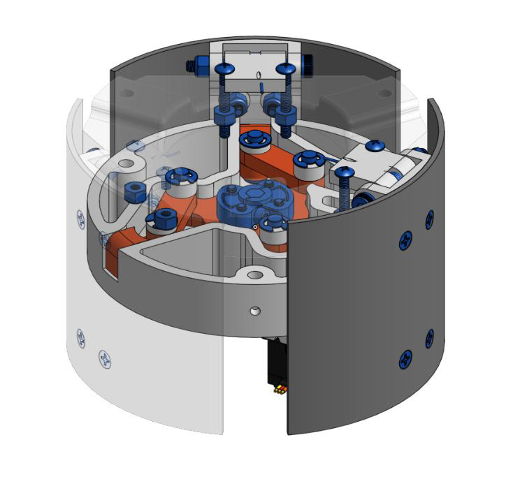
I designed, manufactured, and tested the deployment mechanism which uses torsion springs and magnets to pull the wings open and lock after the payload is ejected from the rocket. On the bottom left are images of the payload linkage system when the payload is folded and unfolded.
The purpose of the payload is to retain four passengers with assumed human survivability and ensure survival after launch and landing. Below is an image of the passengers in their seats with seatbelts, at the front of the payload.
Underside of Unfolded Glider, Photo by Nuri Han
Installing Folded Glider
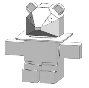
Stemnaut CAD
Stemnaut Seating
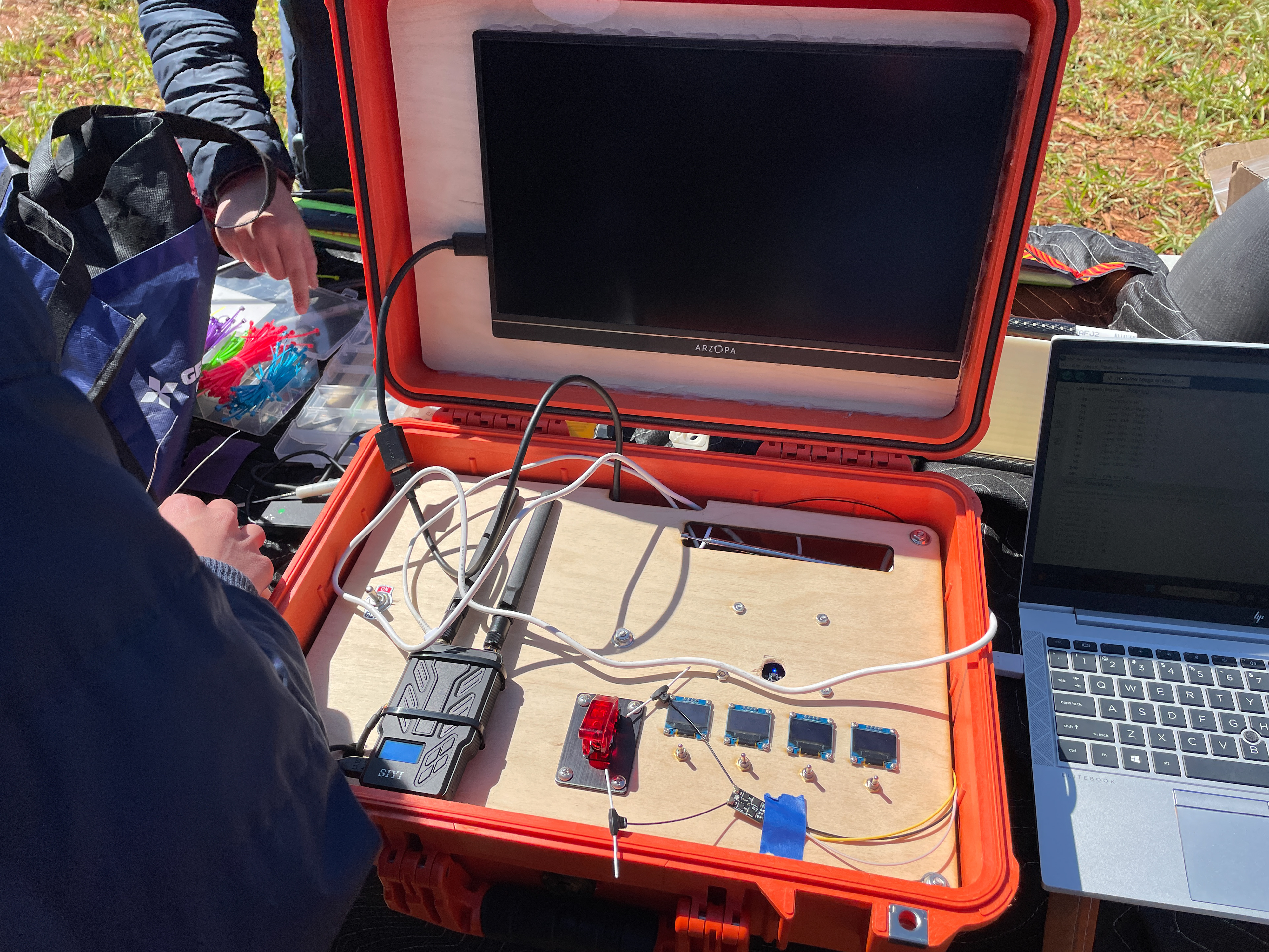
Payload Ground Station
Full Assembly without Flaps
Linkages Visible in Full Assembly
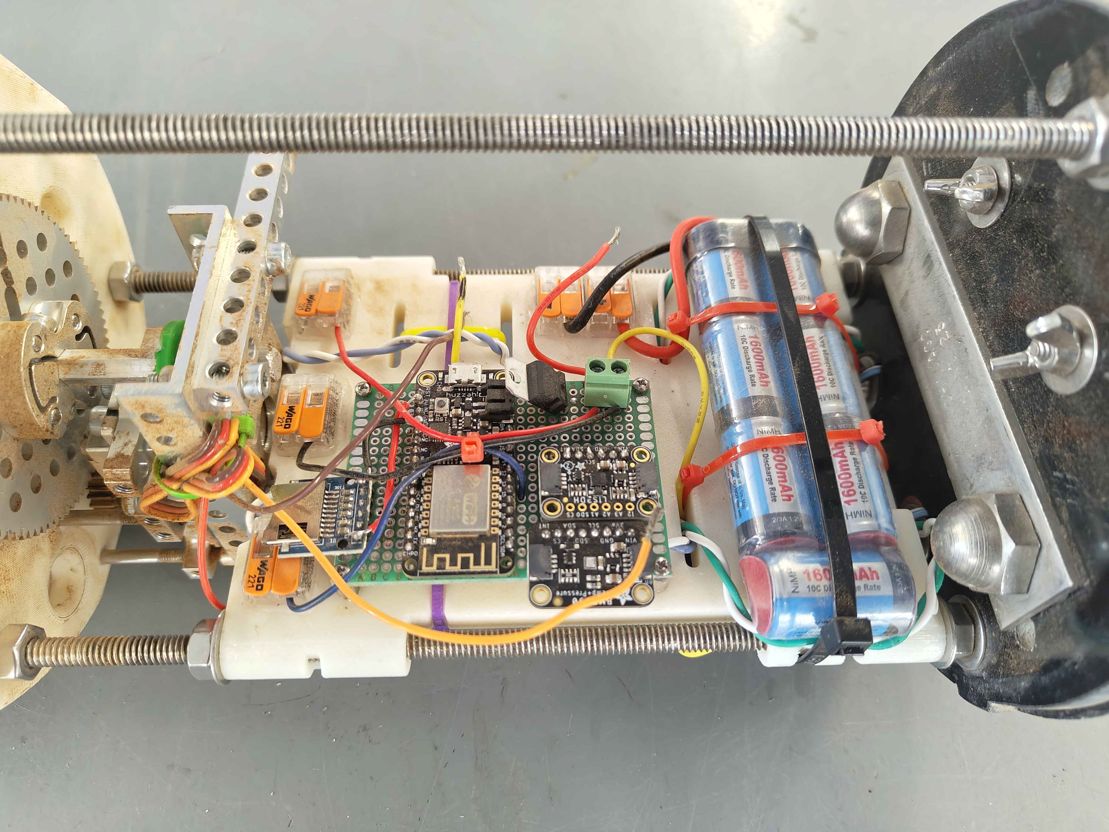
Manufactured Electronics Board
Manufactured Full Assembly
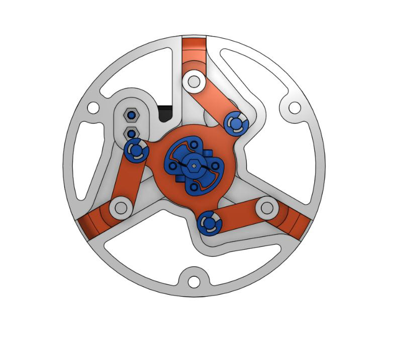
Linkages Closed
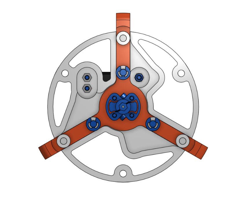
Linkages Open
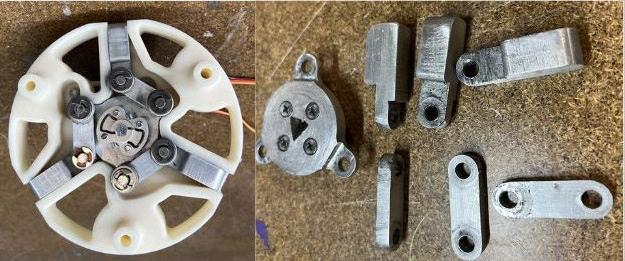
Manufactured Linkage Assembly
AIRBRAKES ENGINEERING SYSTEMS
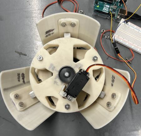
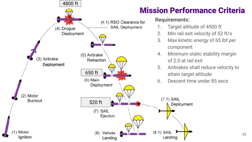
The rocket's propulsion system is designed to overshoot the target altitude, with the airbrakes slowing down the rocket so that it may reach the target altitude. The airbrake system uses a servo to push out a set of flaps to increase rocket drag area. The airbrakes are an independent assembly that can be easily serviced/updated and have two main subassemblies: the flap and linkage modules.
The flap module is stacked on top of the linkage module, and the linkages push out the flaps to a maximum of 40 degrees. I developed the flap mounting system, which uses an inner and outer flap. The inner flaps have a torsion spring which keeps the flaps normally closed. The airbrakes can be slid into the rocket without the outer flaps, which are retained onto the inner flaps using heat-set threaded inserts and screws. I helped create a Python script to model the rocket altitude depending on the flap size and angle, which was verified after fabrication.
The linkage module uses a servo, drivetrain, and linkages to translate rotational motion into linear motion to push out the airbrake flaps. I selected, integrated, and tested a high-torque gearbox to resist the drag force induced by the flaps upon opening. The servo and drivetrain are mounted on the bottom of the module, and drive the linkages with a hex shaft. The module bulkheads have pass-throughs that minimize mass and material waste and allow wires to pass through the airbrakes.
In the video below on the left, the airbrakes deploy to change the rocket's trajectory at 16 seconds, indicated by the wavy smoke trail. The airbrakes decelerated the rocket by 8.5 G's, and the rocket hit its target altitude within 5%.
Airbrakes Deployment Inflight
Airbrakes Actuation Test
RECOVERY ENGINEERING SYSTEMS
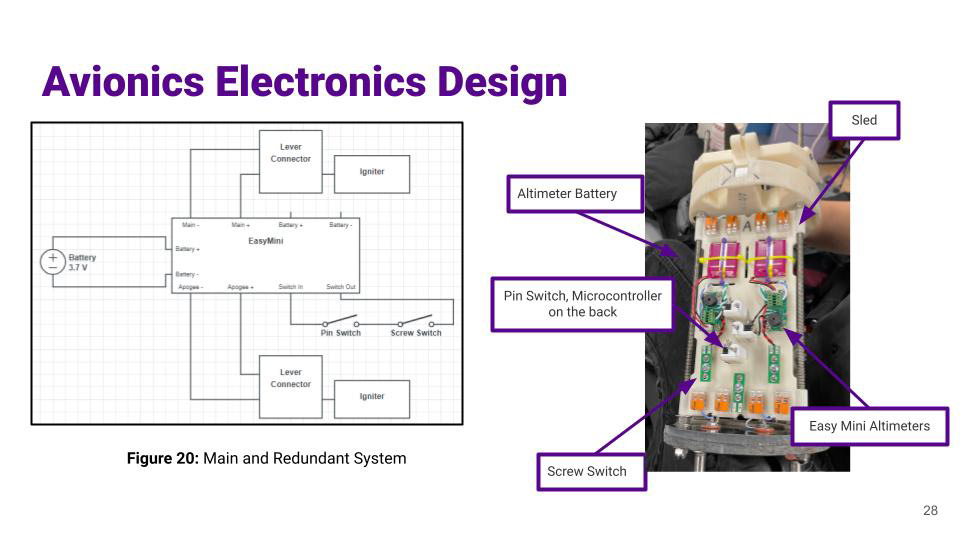
The rocket's recovery system uses black powder to eject parachutes from within the rocket when the electronic sensors detect the appropriate altitude. The electronics are redundant to ensure that the recovery equipment is deployed.
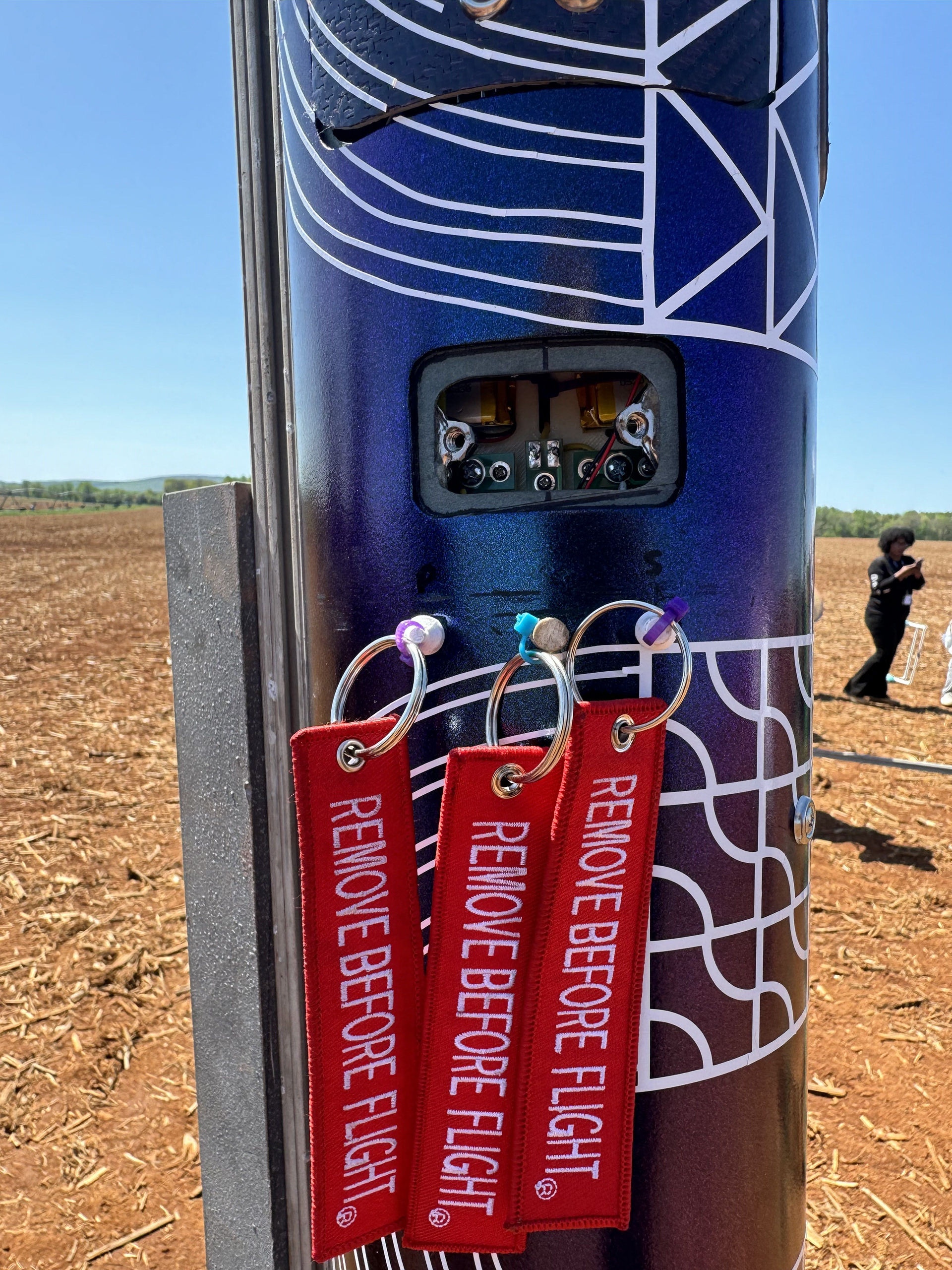
I established a lockout/tagout system with the arming switches using pull tags and screw switches, to prevent the rocket from being armed under unsafe conditions. An image of the screw switch hatch and pullpins can be seen in the top left image.
I designed the igniter passthrough system that allows igniter wires to pass through o-ring seals so that black powder gasses do not pass into the avionics bay. The airbrake flaps can be opened to allow for direct access to electronics and wiring. The entire avionics bay with the airbrakes deployed can be seen in the image on the top right.
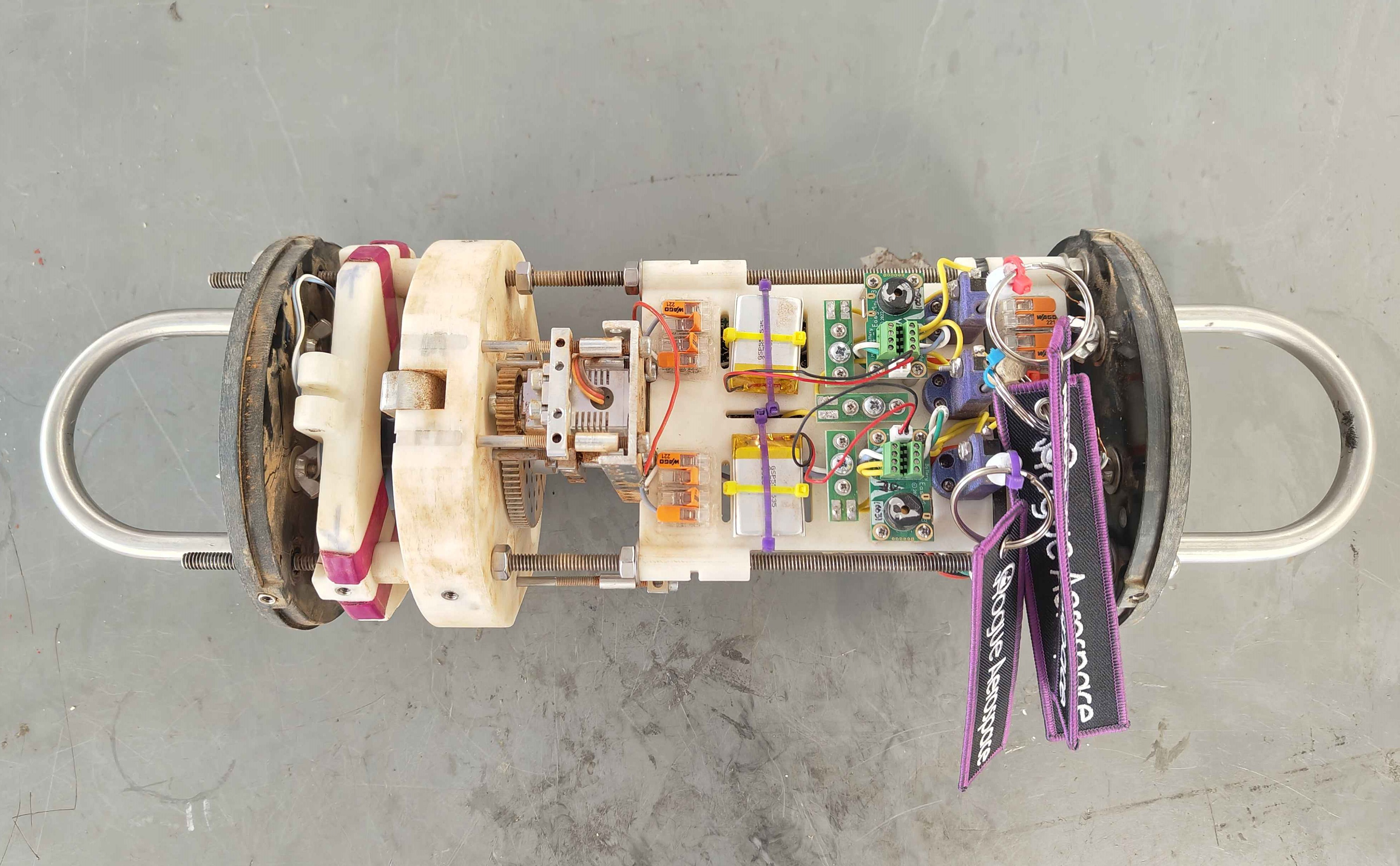
I structured the avionics sled such that flight acceleration will not affect electromechanical connections and component retention while optimizing for safety and maintainability. The entire sled was vibration tested to validate the system before launch.
RBF Tags and Access Hatch

Deployed Airbrakes in Body Tube
Avionics Bay


LAUNCH VEHICLE ENGINEERING SYSTEMS
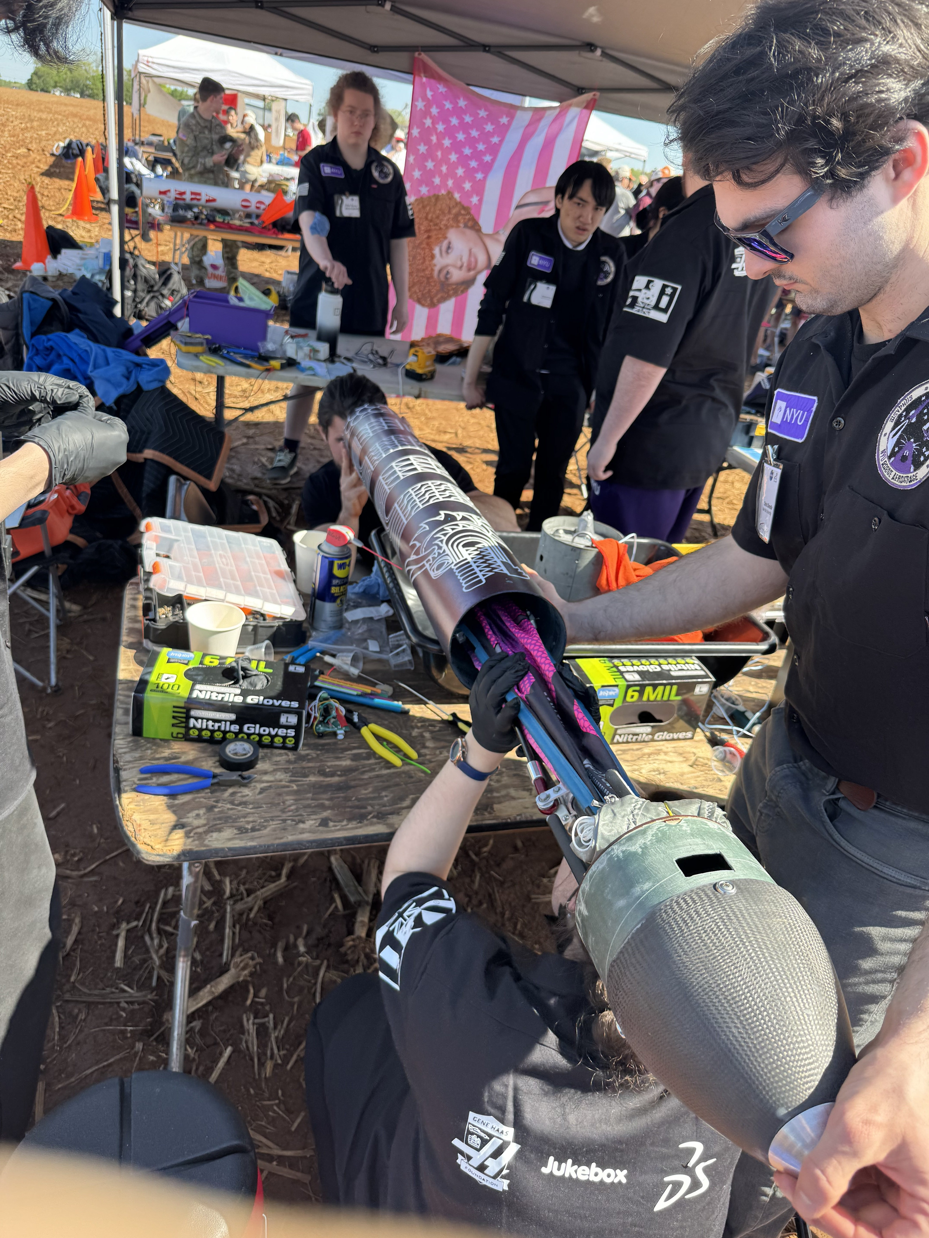
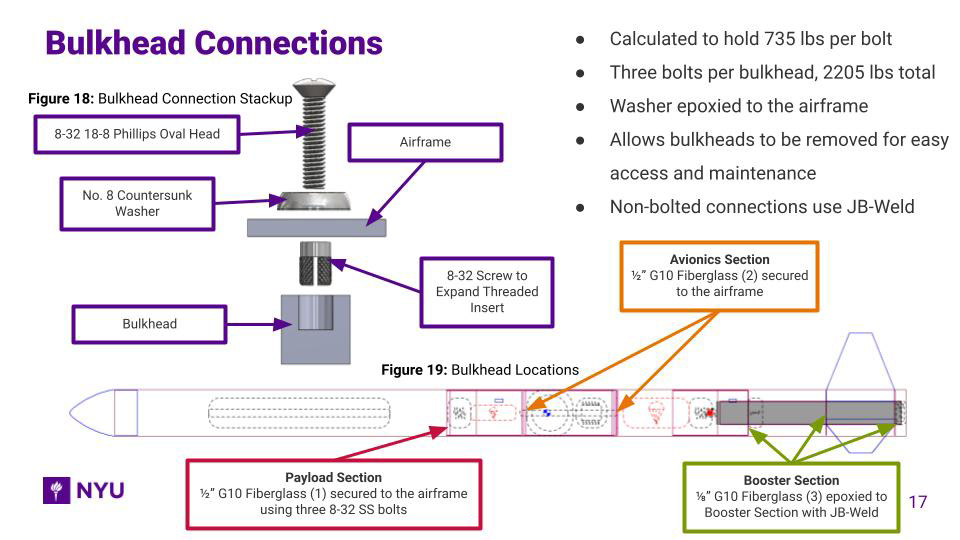
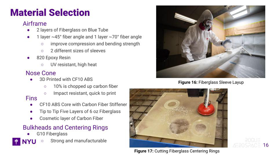
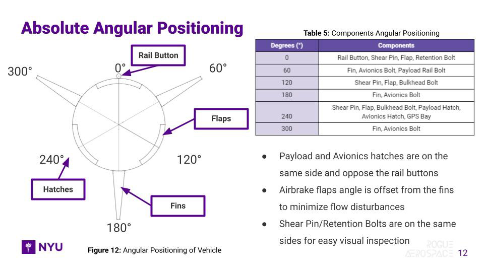
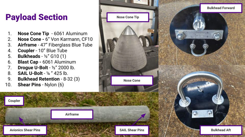
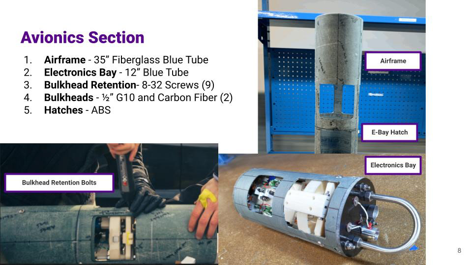
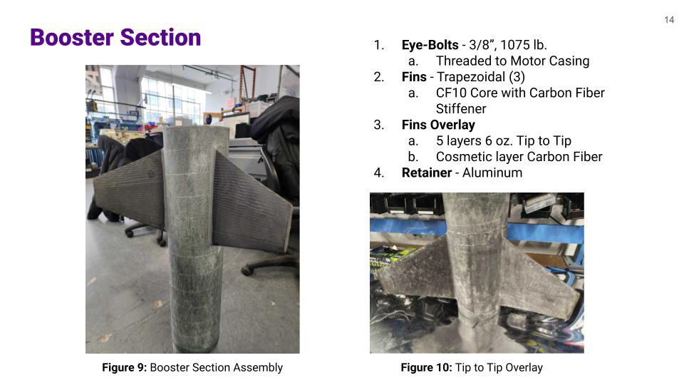
I fabricated the rocket's fiberglass and carbon fiber structural system from scratch and I designed the body tubes and bulkheads to meet the team's strength, weight, and reusability requirements. I developed a novel ballast/payload retention system that uses 1010 rail to align the payload during ejection and hold steel weights to maintain the rocket's stability. The ballasts can be shortened or lengthened, depending on mass changes in other sections.
On the left are selected slides from the Critical Design Review (CDR) and Flight Readiness Review (FRR) presented to NASA The slides depict the various engineering systems on the launch vehicle. Images are not proprietary and are for viewing purposes.
Slides by me
STORY OF SISYPHUS
The rocket and payload are named after the mythological story of Sisyphus. The Greek gods condemned Sisyphus to roll a boulder uphill only for it to roll back down, a cycle that Sisyphus must repeat for eternity. The rocket shares Sisyphus's fate, destined to push the payload into the sky, only for both to fall to Earth.
The mythical nature of the rocket is displayed in its dragon wrap design. The dragon was chosen because the competition year aligned with the year of the dragon in the Chinese zodiac. Furthermore, the rocket flies in the sky and spits fire when it ejects the payload. The dragon decal, smooth fiberglass job, exposed carbon fiber, and shiny paint job led to the team winning the annual Best Looking Rocket Award.

Design by Quarta, Modified by Me
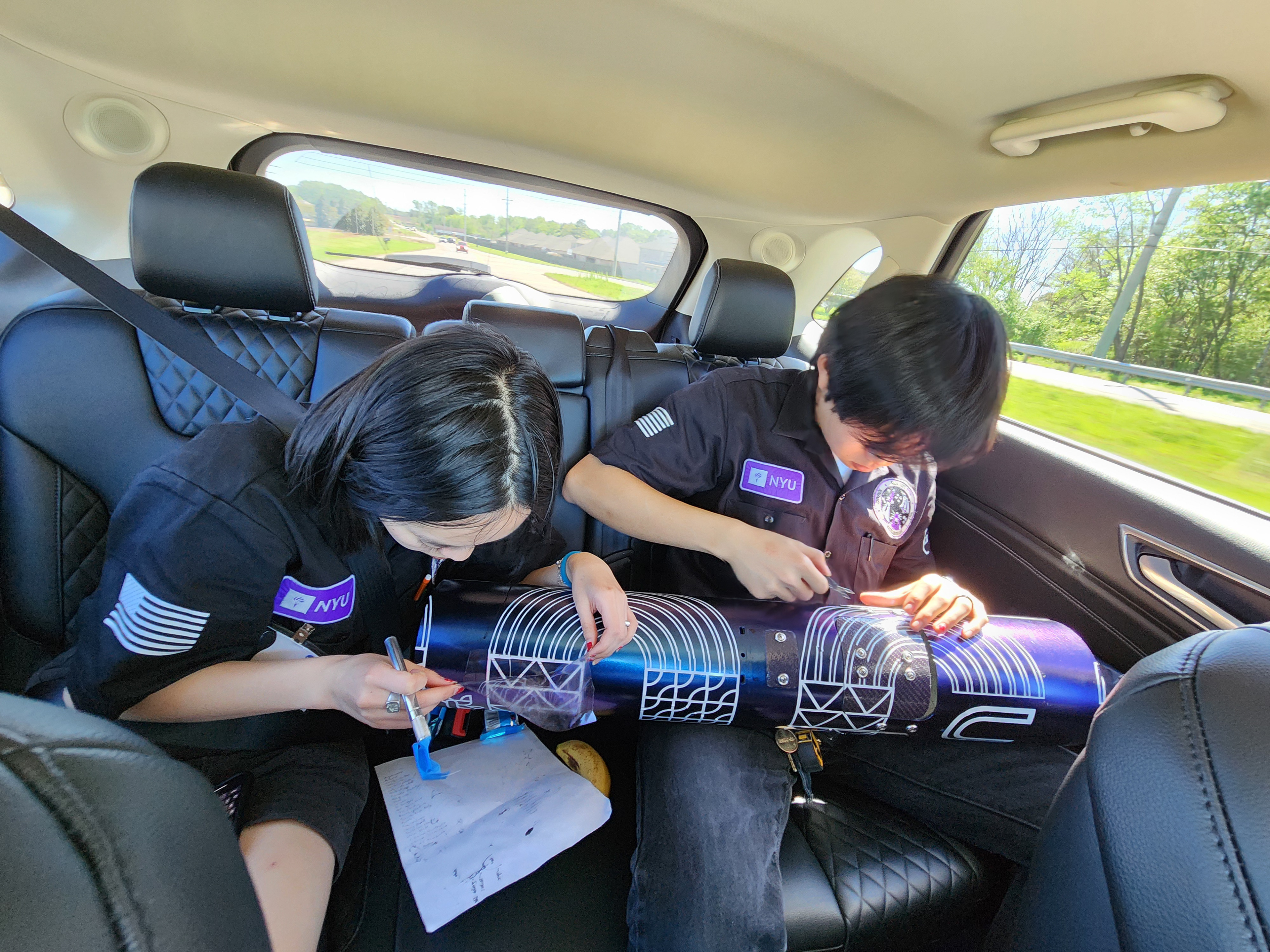
Applying Decals in the Car